SimpleBot Chassis Assembly
Contents
SimpleBot Chassis Assembly
Now the SimpleBot shield is built, the next step is to build the SimpleBot itself.
Chassis Parts
The main chassis of the SimpleBot is made from a corrugated plastic called CorFlute, which is cheap and fast to laser cut. The SimpleBot creator, [Andrew Fisher], came up with this design.
There are two pieces - a large base plate, and a smaller front bumper plate.
You may have to press out some of the cutouts from the plates, that the laser cutter didn't cut all the way through. A screwdriver or a craft knife will help with any particularly stubborn pieces.
After all the cutouts are removed, the front bumper clips onto the base plate like this:
The pieces are both symmetrical so there is no "wrong" way to attach them.
Mount Raspberry Pi
After clipping on the bumper, we screw the Raspberry Pi onto the base plate on top of 10mm high standoffs.
Take care when mounting the Raspberry Pi as it is sensitive to static discharge. Ground yourself before handling it.
The standoffs you'll have are slightly different to the ones shown in this picture. The actual standoffs have a female threaded hole in the bottom and a male threaded extension at the top.
Mount the standoffs onto the four small holes in the base plate:
Use the four short nylon bolts to screw the standoffs into place through the bottom of the plate.
Once the standoffs are firmly mounted, place the Raspberry Pi on top and screw it down using the nylon nuts. The USB ports on the Raspberry Pi should point forward, towards the front bumper.
Continuous Rotation Servo "Motors"
The motors for the SimpleBot are continuous rotation hobby servo motors.
Flip the chassis assembly over so the Raspberry Pi is facing down, as the motors and battery pack are mounted on the bottom.
The servos are aligned with square mounting holes, like this:
The shaft on each servo should be closest to the front of the SimpleBot, near the bumper.
Each servo is held on via two cable ties. Each cable tie run through the mounting holes, around the servo.
Here's a close up of one side of the SimpleBot:
And the other side:
In these photos the cable ties may be a little too tight, as the CorFlute base has bent a little at the side. This doesn't really matter, but they don't have to be this tight!
Battery Pack
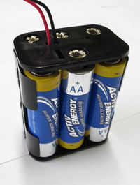
The 6 cell battery pack is also mounted using two cable ties to form a "cradle" under the robot base. Unlike the servos, you want the battery "cradle" to be a bit loose so you can pull the pack out to change batteries.
Start by screwing the two leads from the battery pack into the DC jack:
The photos shown here use a different DC jack, but the principles are the same.
Then insert the Alkaline AA cells in the pack.
IMPORTANT: Once the batteries are installed the DC jack terminals carry 9V, and can potentially damage electronics if they brush across them. Take care not to rest the DC jack against any of the electronics! It should sit out to the side away from the rest of the robot.
With the SimpleBot base upside down, place the battery pack between the two servos. The lead should come out towards the rear of the robot, pointing away from the front bumper.
The cable ties to form the "cradle" need to go down via the mounting holes on each side of the chassis plate, under the Raspberry Pi. This can be a little bit fiddly, it may be helpful to place the battery pack to the side after sizing it up, and then insert it once the cable ties are loosely inserted.
From the top side of the SimpleBot, the battery cradle cable ties will look like something this:
Wheels
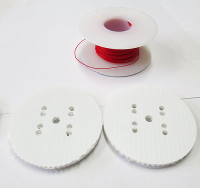
The SimpleBot has two wheels, and each wheel is made up of a sandwich of two pieces of CorFlute. The wheels are held on via fine wire, we're using "wire wrap" wire for electronics.
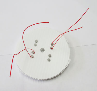
Cut two medium length pieces of wire, and run each through opposite holes.
Each wheel is made up of two identical pieces of CorFlute.
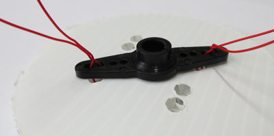
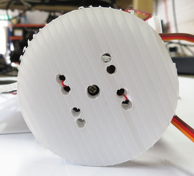
On top of each wheel, run the wires through the "servo horns" that mount on the servos:
The central mounting hole on the horn should line up with the hole in the centre of the wheel:
Once everything is lined up, tie the wire ends down and cut them off.
NOT SHOWN: For the "cross" type servo horn, repeat the process on the other two corners to make a stronger binding between the horn and the wheel. On the "straight" type horn that is shown, you probably also want to run some wire across the horn to bind it as tightly as possible to the wheel.
Repeat for the second wheel.
After you think both wheels are securely tied onto the servo horns, mount the servo horns on the servos and screw them down in the centre:
"Sled"
Unless you want to update your SimpleBot to become a "BalanceBot", it will need something for the chassis to balance against on top of only two wheels.
As another low cost improvement, the SimpleBot uses a simple cable tie to form this "sled". Forming the "sled" is a little tricky to explain, don't be afraid to go and look at a completed SimpleBot in order to understand.
Start by flipping the robot upside down, and push a cable tie through the end two sled mounting holes as shown, with the "tab" on the inside of the two holes:
Take the outer end of the cable tie and wrap it all the way over the top, through the innermost mounting hole, then back through the adjacent hole. You have to push the tab down as you go:
Once you're sure it's looped OK, push the end of the cable tie into the tab. Don't tighten it right up yet! You need to check the height is OK.
Flip the robot over, and adjust the cable tie until the robot seems to sit flat on the "sled". Then cut off the end of the tie:
PiLeven
Mounting the PiLeven is fairly straightforward, it just presses down onto the Raspberry Pi header as shown:
SimpleBot Shield
Mounting the SimpleBot Shield is also straightforward, it drops onto the PiLeven as shown:
Connections
Mount the Ultrasonic Rangefinder sensor by dropping it into the 4 pin header at the front of the SimpleBot.
Connect the servo motors by feeding the connectors through the small holes in the base plate, then plugged them into the two "motor" headers. The yellow "signal" wire faces towards the front of the bot, as shown.
Connect the Wifi adapter by plugging it into a USB port on the front. In the position shown, the antenna doesn't interfere with the Ultrasonic rangefinder (although the rangefinder does appear to detract from the wireless reception a little bit).
Power Connection
The battery pack plugs directly into the DC jack on the back of the PiLeven. Don't plug it in until you've prepared the SD card to boot up the Pi. Removing the DC jack connection will power down the Pi immediately, so we suggest shutting down Linux if possible before doing this.
All Done
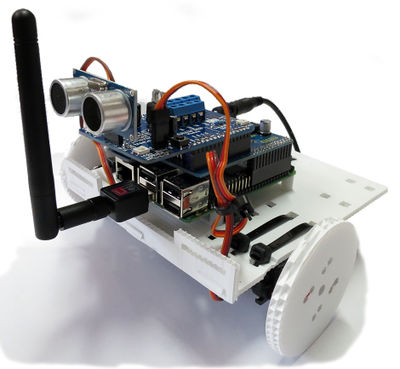
Congratulations, you built a SimpleBot!
Next step is to prepare the SD card and perform the SimpleBot Initial Software Configuration.


