ArduPhone
Contents
Hardware Assembly Project: ArduPhone
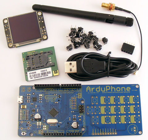
The hardware assembly project this year is designed to be easy for beginners to put together, even if they haven't soldered before, while still resulting in an amazingly cool end result. The ArduPhone design uses mostly surface mount parts which are all pre-fitted, leaving a small number of through-hole parts for you to solder on. You'll need to fit some connectors, solder in some buttons, and clip on some modules that contain most of the functionality pre-assembled and tested, so even if you're a total beginner to hardware hacking you'll end up with a working ArduPhone by the end of the miniconf.
An early prototype and unfitted parts:
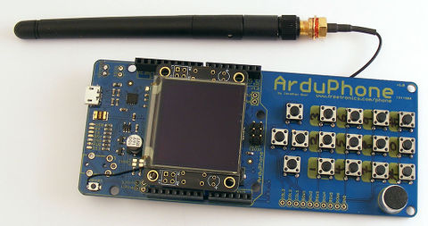
Prototype with screen, GSM module, buttons, and antenna fitted:
Features:
- Arduino-compatible: run your own firmware, have 100% control of the phone
- ATmega1284P MCU running at 3.3V, 8MHz. Custom board profile provided for Arduino IDE
- Onboard smart LiPo charger
- Charges from USB (variable charge rate to suit different batteries)
- 128x128 OLED display
- ADH8066 GSM module (quad band GSM/GPRS)
- Microphone and speaker connections for voice calls
- Send and receive SMSs, and load web pages
- Arduino headers so you can add more I/O: build it into your own project!
- PCB can be cut in half to remove keypad
Note: SIM card NOT provided! You can get a pre-paid SIM for the ArduPhone before the conference, or temporarily install your own SIM for testing.
The complete ArduPhone kit will be $110, which includes everything required: main PCB, OLED display module, GSM module, antenna, even a USB cable.
Note that GSM ("2G") coverage is mostly limited to metro areas and major towns and highways, so it won't work in many areas where only 3G coverage is available. You can check Telstra 2G coverage using the map at www.telstra.com.au/mobile-phones/coverage-networks/our-coverage/ by selecting 2G in the "Network Type" option.
Useful AT Commands
The ADH8066 GSM module is controlled using old-school AT commands. These are some handy ones to know, and your sketch can send them to the module to control it.
AT: Get attention of the module. It should respond "OK".
ATDxxxxxxxx: Dial the number.
ATA: Answer an incoming voice call.
ATH: Hang up a voice call.
AT+CSQ: Check Signal Quality. Returns two numbers, comma separated. The first number is signal strength. 0 is no signal, 31 is maximum possible reading. Anything from about 12 up is OK.
AT+IPR?: Check Interface Port Rate (baud rate of the serial port). By default the ADH8066 is set to 115200, but the ArduPhone MCU can't talk that fast while running at 8MHz so the rate has been changed to 9600.
AT+IPR=9600: Set the Interface Port Rate. The module will then restart its comms. Don't set this too fast or the ArduPhone MCU won't be able to keep up.
AT+SFUN=OFF: Special FUNction = OFF. Powers down GSM module.
AT+SFUN=RST: Special FUNction = ReSeT. Resets the GSM module.
AT+SFUN=VER: Special FUNction = VERsion. Returns the GSM module firmware version.
Discussion Forum
There is a dedicated section of the Freetronics forum for ArduPhone. Please post questions, updates, firmware changes, projects etc there:
Sticky Battery Connector
The 2mm JST connector used on the battery has a clip that holds it very tightly in place, making it very difficult to remove. Be very careful when disconnecting the battery so that the wires don't pull out.
The connector attached to the battery has two tiny ridges on the top that latch it in place. You can use a knife or side cutters to trim down one or both of the tabs, making it much easier to remove. The connector will still be held in place by friction so it shouldn't fall out.
Wiring Microphone Jack
Unfortunately, there is a mistake in the headphone socket pinout so it can't be used directly. As described in the Assembly Guide, a single-ear earpiece can be soldered in the top right of the PCB. Besides, it is still possible to connect the sockect pinout using some jumpers. For the socket in the diagram, the following connections can be made:
SIG: connected to the + pad of the Speaker in the top right of the PCB.
GND: connected to the - pad of the Speaker in the top right of the PCB.
MIC: connected to the MIC jumper pad (left one).
ArduPhone Architecture
This is the final slide from Jon's talk about the overall architecture of ArduPhone.


